![]()
Introduction:
For over 10-years the Lincoln County Lake Norman Water
Treatment Plant stored the plant’s backwash water and settling basin solids in
a concrete tank originally built to store finished water.
The water plant utilized a one million gallon prestressed concrete tank
that was built for finished water storage to hold the water plant solids.
An accumulation of sludge in the tank over the years created a burdensome
problem that was solved in 2001 with a solids handling project that allowed the
prestressed concrete tank to be converted back to it’s intended use as a
clearwell.
Background:
Lincoln County was formed in 1779 from Tryon County.
It is in the southwestern
section of the State and is bounded by Mecklenburg, Gaston, Cleveland, Catawba
and Iredell counties. The County
draws water from Lake Norman, a manmade reservoir on the Catawba River located
on the eastern boundary of the County. The
lake water is treated at the County water treatment facility, located adjacent
to Lake Norman, and the treated water is distributed throughout most of the
County to over 7,000 customers. Raw
water turbidities range from 3 to 24 NTU with an average turbidity of 8 NTU.
The raw water contains very little natural solids.
Solids removed in the treatment process are mostly chemical solids from
chemicals used to treat the water. Collected
water samples showed poor settling characteristics under lab conditions with a
dry suspended solids content of 0.43%. A
sludge sample only thickened to a dry solids concentration of 0.86% after
settling 24-hours.
The
water plant is currently configured to pump raw water from the lake through a
series of flocculator tanks, rectangular shaped gravity settling basins and dual
filter tanks. Solids that are
settled out in the settling basins are removed from the floor of the basins with
a vacuum sludge removal mechanism that sweeps the floor at preset intervals set
by a timer controller. Typically the
basins are swept once a day for a period of approximately 20-minutes each.
About 30,000 gallons of water, or 1% of the water treated daily, is
wasted with each cleaning of solids from the basins.
The second source of solids generated by the water treatment process is
from backwashing the gravity filters. Currently
there are two filter beds. Each
filter requires about 50,000 gallons of process water to backwash, 1.7% of the
treatment plant capacity. Prior to
2001, when the vacuum beds and gravity thickeners were placed into service, all
backwash water and settling basins solids was gravity drained and stored in a
1.0-MG prestressed concrete tank originally constructed to store finished water.
Over the first 10 plus years of operation the solids were stored in the
tank. The water plant operators
would periodically draw supernatant off the tank and return the water initially
through the water plant and later to Lake Norman with a NPDES discharge permit.
The solids remained stored in the tank over this period of time till the
tank was in effect full and something else had to be done.
In March of 2000 the County ask WK Dickson to help
find a solution to the water plant sludge problem.
Working with the water plant ORC, Mr. Larry Warren, and the County
Engineer, WK Dickson evaluated various alternatives to handling solids including
belt filter press, centrifuge, vacuum drying beds and gravity drying beds.
Sludge dewatering proposals were received from major equipment
manufacturers and site visits were made to various water plants using a variety
of sludge dewatering methods. After
evaluating all alternatives both the belt press and vacuum beds were found to be
viable alternatives for dewatering the sludge.
Centrifuges and gravity beds was eliminated as viable alternatives early
in the evaluation as a result of equipment costs, performance data and
discussions with other users. Both
the belt press and the vacuum bed manufacturers showed through lab pilot testing
to be able to dewater the Lincoln County sludge to a 15% dry solids, producing a
dry cake that will pass a paint filter test.
Present work cost analysis showed the belt filter press and vacuum bed
cost as follows:
| Construction Cost | Annual O&M Cost | Present Worth Cost | |
| Belt Filter Press | $1,039,700 | $33,800 | $1,397,800 |
| Vacuum Beds | $865,700 | $30,575 | $1,189,600 |
Bids were received in December 1999 and Ray Smith Construction Company of Newland, NC was the low bidder. Construction of the facilities was completed in June 2001 for a total cost of $1,110,269.
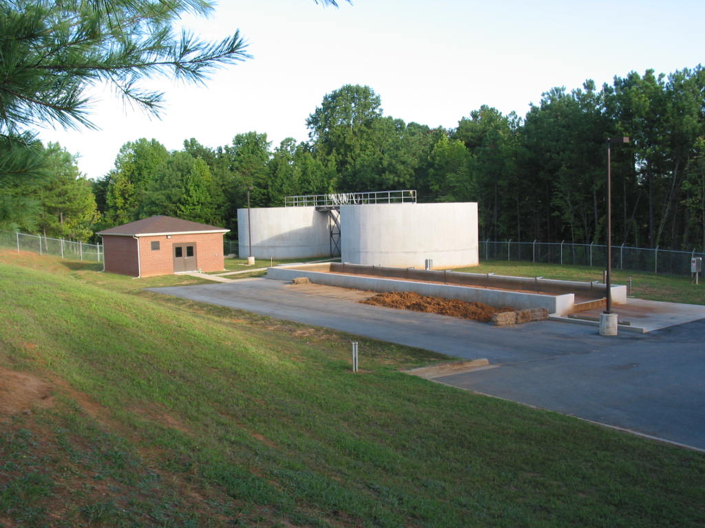
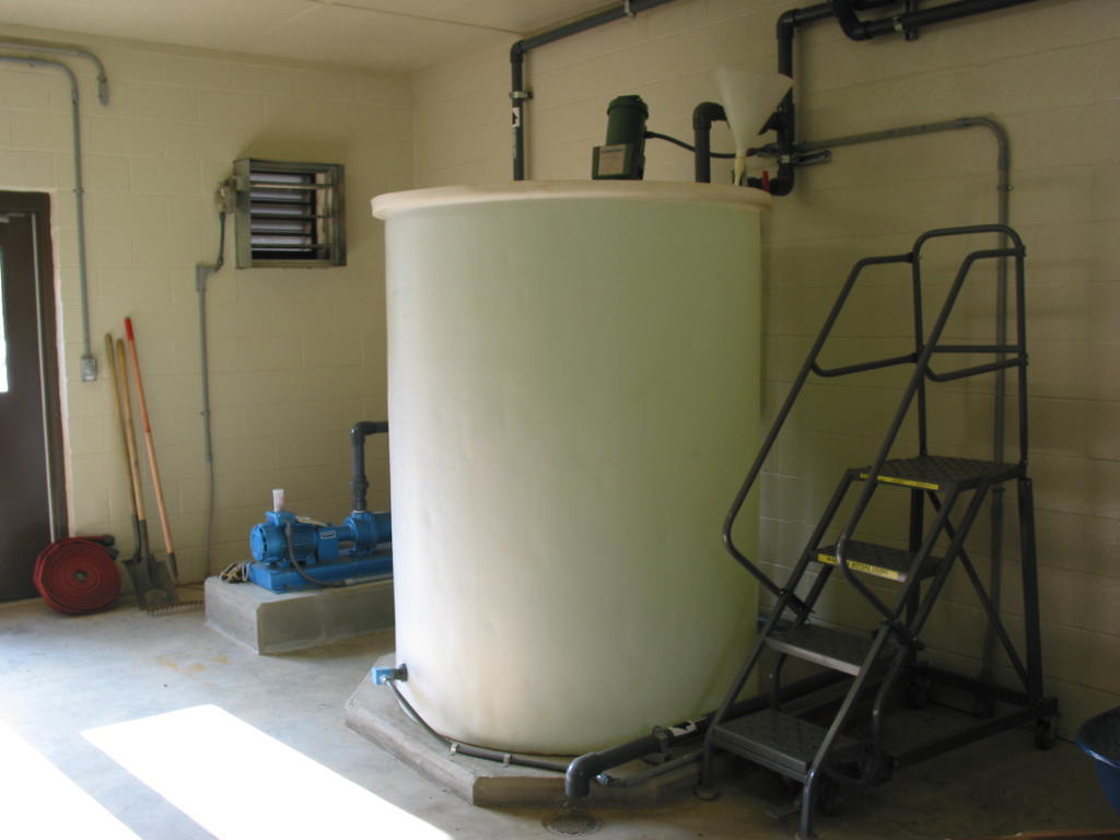
The sludge handling facilities includes; two gravity
thickener tanks, one vacuum drying bed and a building housing; controls, sludge
pump, vacuum pump and a polymer feed system.
The backwash water and sludge vacuumed from the settling basins flows by
gravity to the thickener tanks through a 20-inch pipe.
Piping and valves are provided to enable the two tanks to work together
or as separate tanks to store the sludge until dewatered.
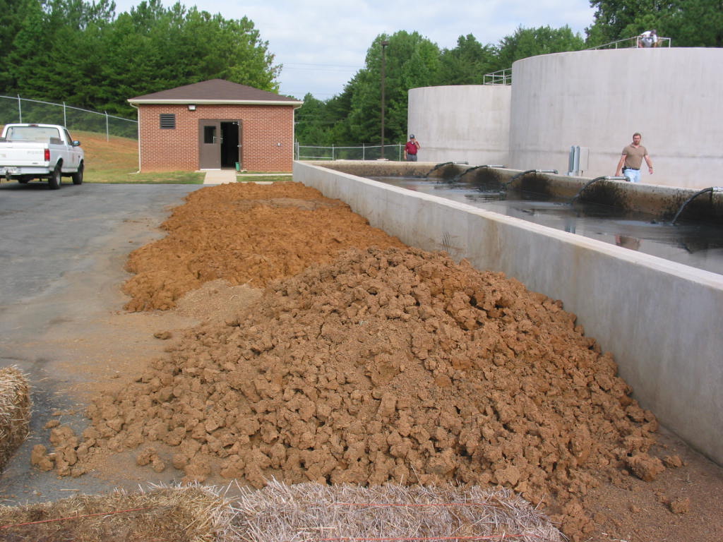
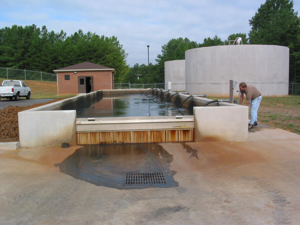
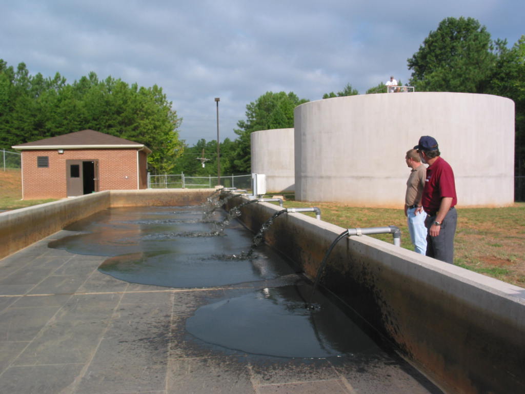
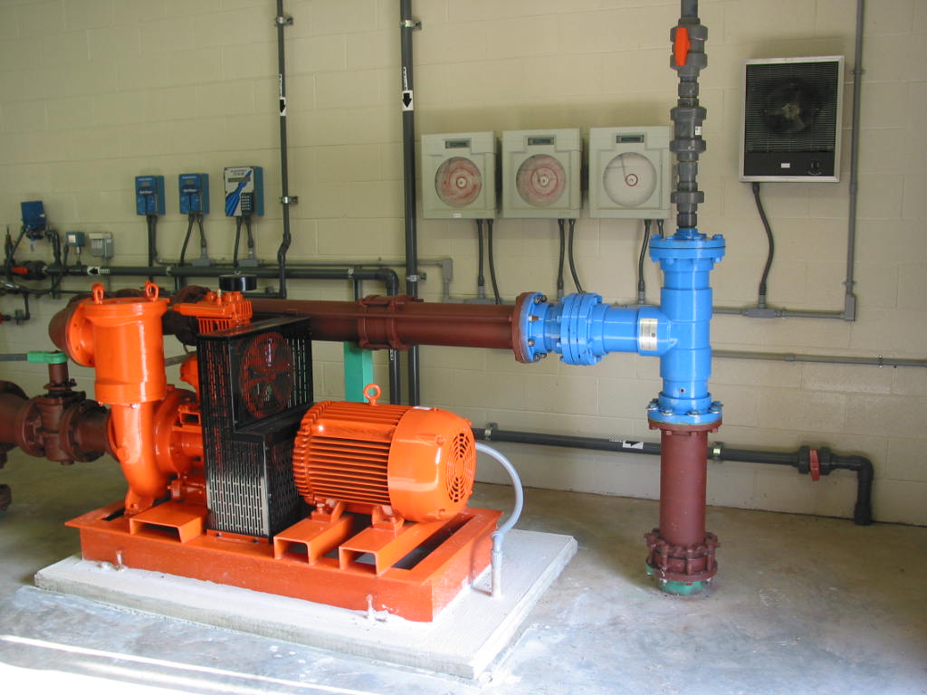
The settled sludge is drawn from the bottom of the thickeners by a
centrifugal pump and spread over the vacuum drying beds using a total of seven
2-inch discharge pipes with valves to distribute the sludge over the bed.
Supernatant is drawn from the thickener tanks and discharged to Lake
Norman through a 12-inch gravity drain. A
vacuum pump and polymer system is available to dewater the sludge on the beds.
The sludge filtrate is returned to the gravity thickeners through an on
site pumping station and force main. The
dried sludge is removed from the beds with a small bobcat and trucked to the
County’s solid waste site for disposal.
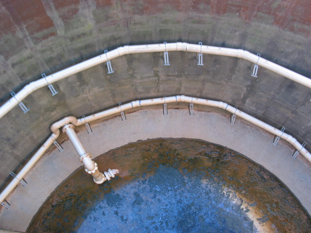
Gravity
Thickener Tanks: Each tank is 35-feet in diameter with a 22’-3” vertical
side water depth and a 10’-10” conical bottom..
Each tank can store 199,000 gallons.
Two 6-inch perforated pipes ring the diameter of the tanks above the
conical bottom at two different levels to remove the supernatant after the
sludge has settled. The supernatant
is drained through a 12-inch pipe and discharged directly into Lake Norman.
Piping and valves are available to control flow to the two tanks and to
transfer sludge between the two tanks. A
8-inch suction pipe is provided to draw sludge from the bottom of each thickener
with a 700 gpm sludge pump.
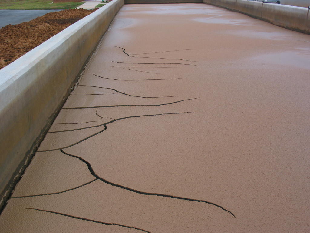
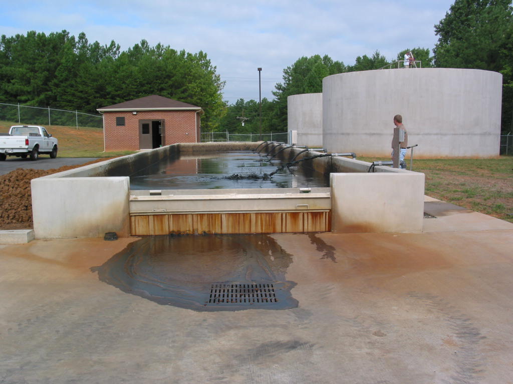
Vacuum Drying Bed: a 1,240 square foot vacuum bed sized for 6.0-MGD of treatment capacity is provided. The bed is 16-feet wide by 76’-8” long with seven 2” feed pipes equally spaced along one side of the bed. An 8-inch filtrate drain runs the length of the bed and is gravity drained to an on site submersible pumping station. The filtrate is drawn off the tank and pumped back to the gravity thickeners. Polymer is blended with the sludge when the vacuum bed is loaded from the thickener. A 2-hp vacuum pump is tied to the filtrate drain under the bed and operates to draw a vacuum on the bed after the operator loads the bed from the thickener tank. U.S. Environmental Products, Inc. furnished the vacuum drying bed and associated equipment.
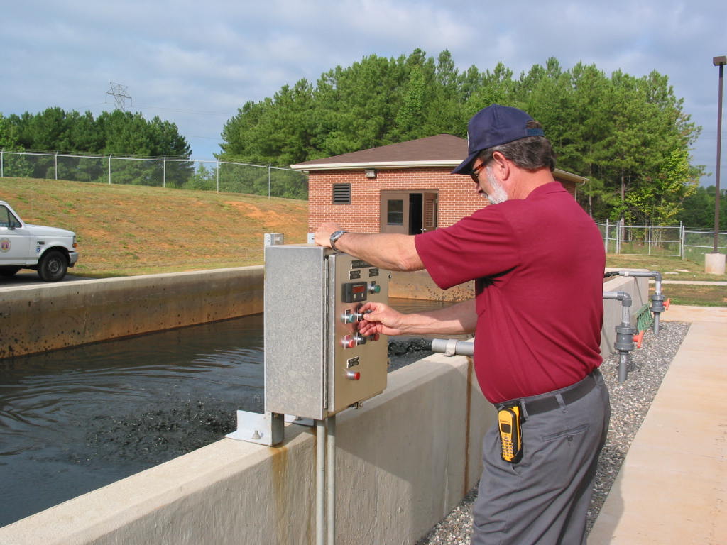
The operators store sludge in the gravity thickener
tanks until they are ready dewater the sludge.
The sludge settled out in the conical bottom of the thickeners and the
supernatant is drained off and discharged back to Lake Norman.
Currently, the operators control the supernatant removal manually.
There are also timer controlled valves provided to allow supernatant
drains to open and close with a 24-hour time clock.
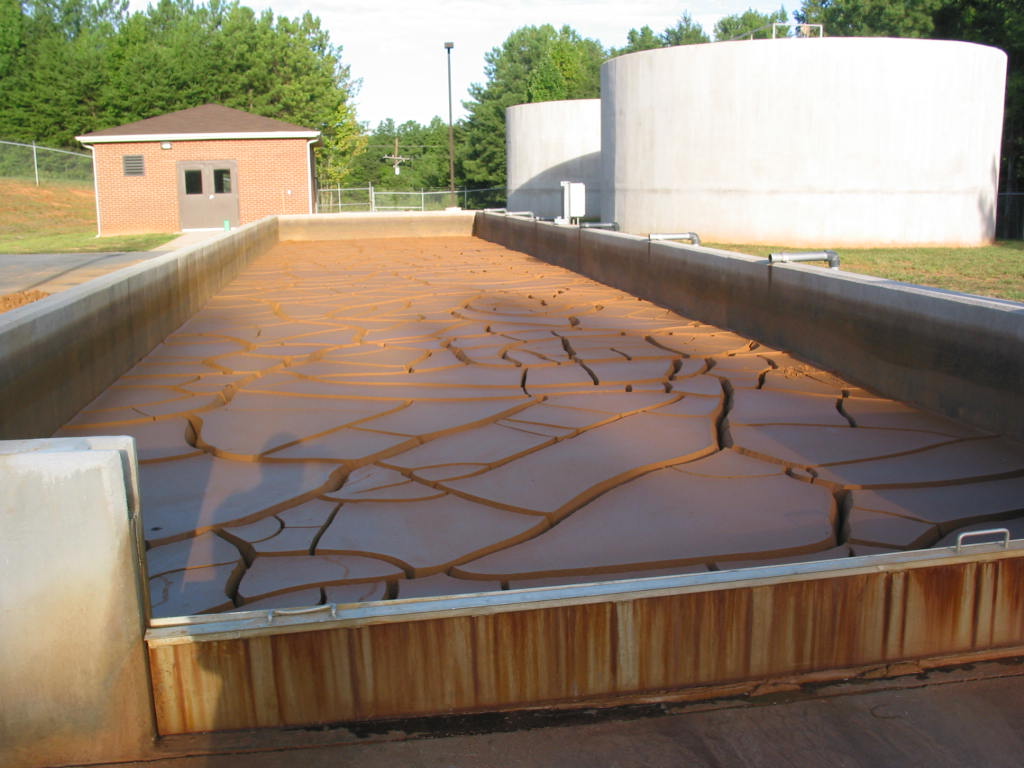
The vacuum bed has proven to be an effective method to
dewater sludge at the County’s Lake Norman water plant.
The sludge handling project has allowed a much needed clearwell tank to
be converted from a sludge storage tank to its intended use.
Key to a successful system is having effective gravity thickener tanks to
store sludge until the operators are ready to dewater the sludge.
Also key are sludge pumps and controls to allow the operators to easily
remove the sludge from the thickeners and transfer the sludge to the vacuum bed
for dewatering.
WK Dickson
616 Colonnade Drive
Charlotte, NC 28205
704-334-5348
704-334-0078 (Fax)

![]()